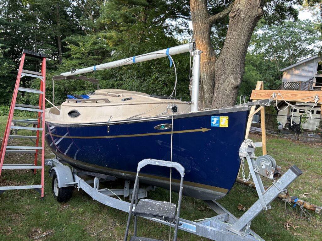
The Com-Pac Sun Cat is a 17-foot, trailerable catboat with a tabernacle mast.
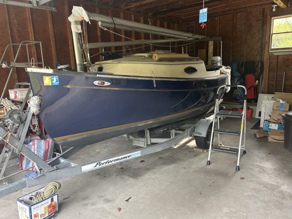
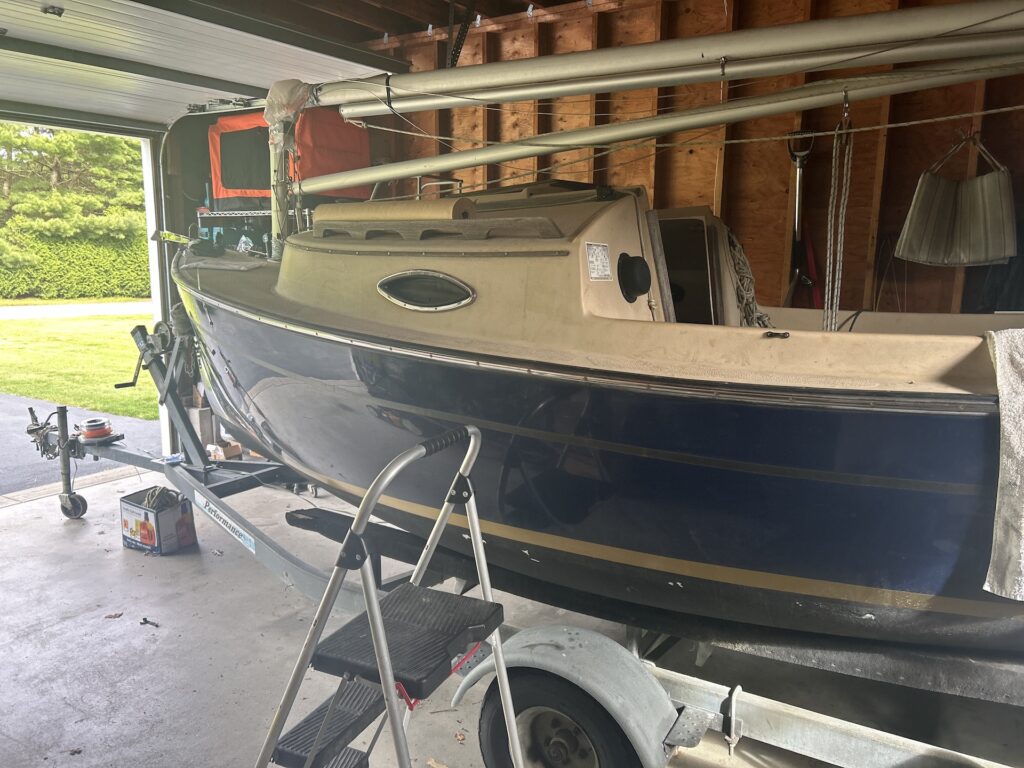
The owners purchased the boat recently and have not yet sailed her. The hull and rig are structurally sound, but the owner wanted the interior spruced up. The scope of the project expanded somwahat as work progressed, as you will see.
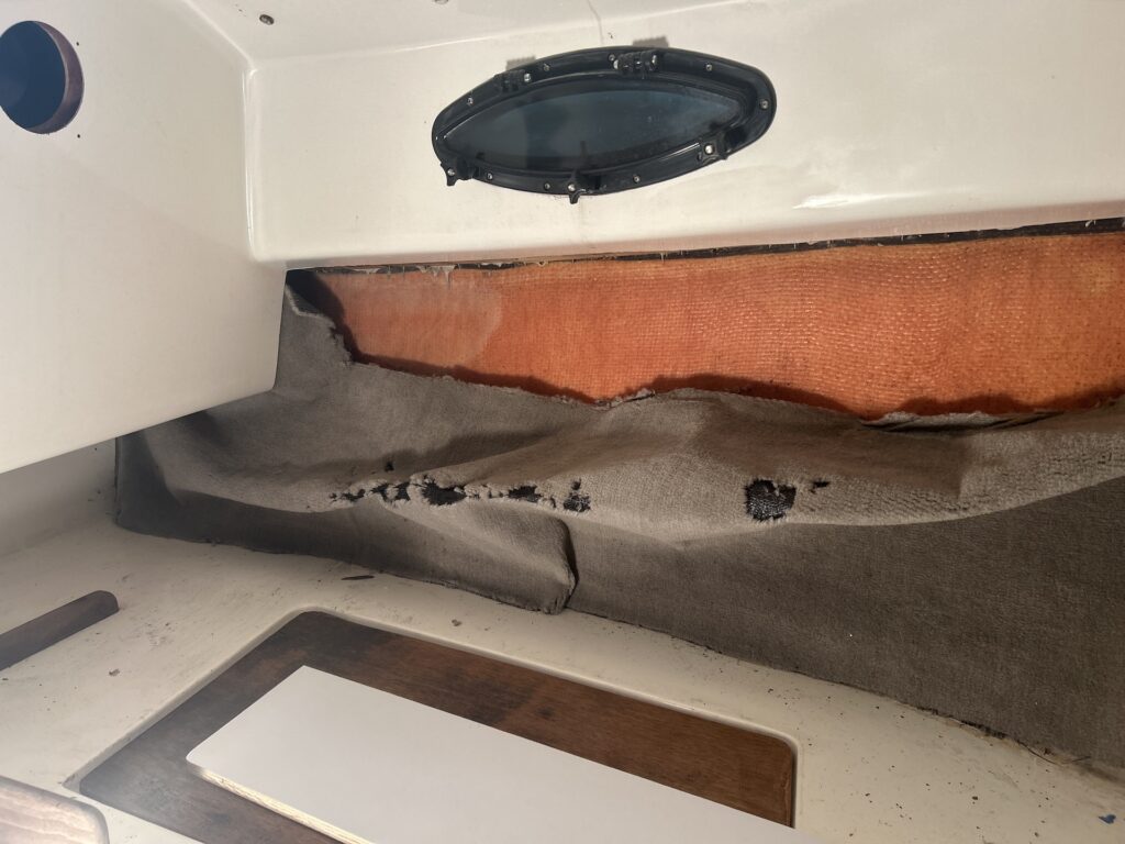
Inside the boat, the hull was originally lined with carpet and you can see that it had become dilapidated:
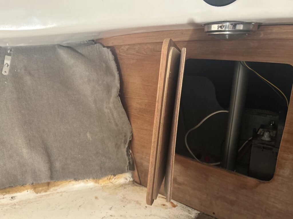
You can see below that the chainplates were installed in such a way that they sandwiched the rug against the hull.
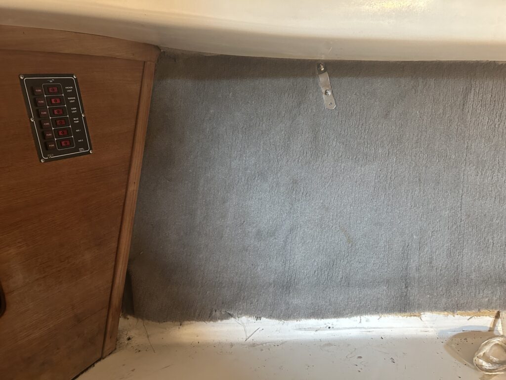
The first order of business was to remove the chainplates, then the rug, then rebed the chainplates.


There is a bulkhead the separates the main cabin and the forepeak. The forepeak contains a chain locker and a small area where the battery lives. The original bulkhead was badly delaminated, and generally not well, so it needs to be removed and replaced. It’s not a structural bulkhead, and therefore was not glassed to the hull, so removal was fairly easy.
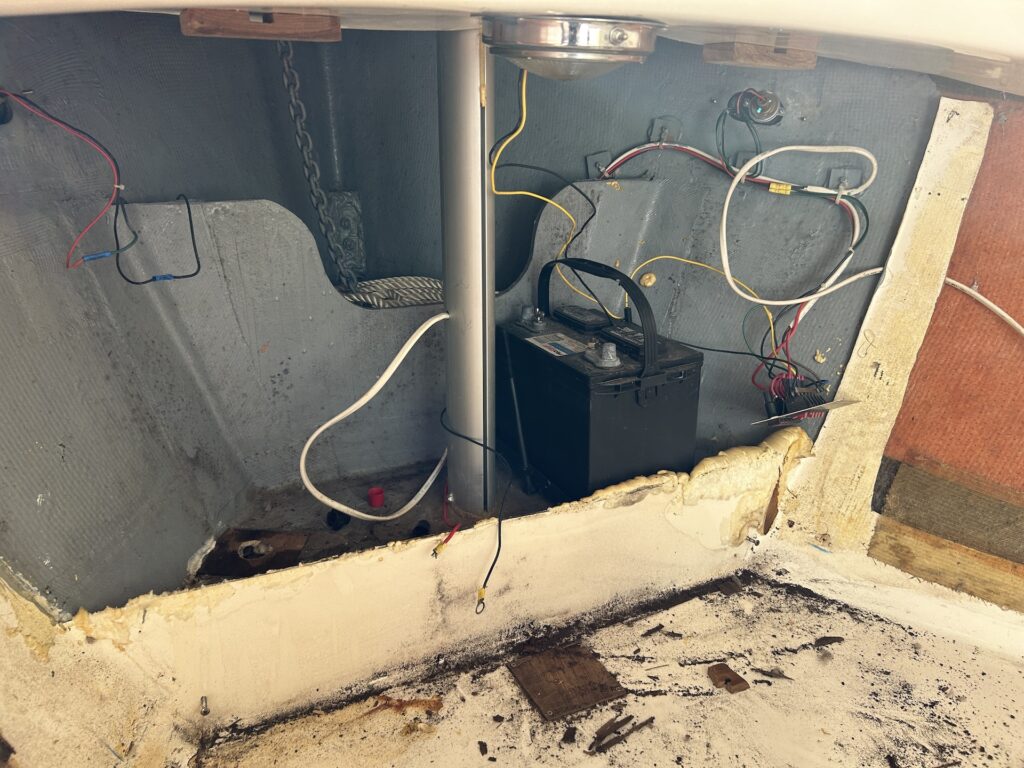
With the bulkhead removed, the area forward of it could be accessed with ease. The small square of rotted wood just aft of the forward area is a cover for a hole in which expanding flotation foam was poured in the build.
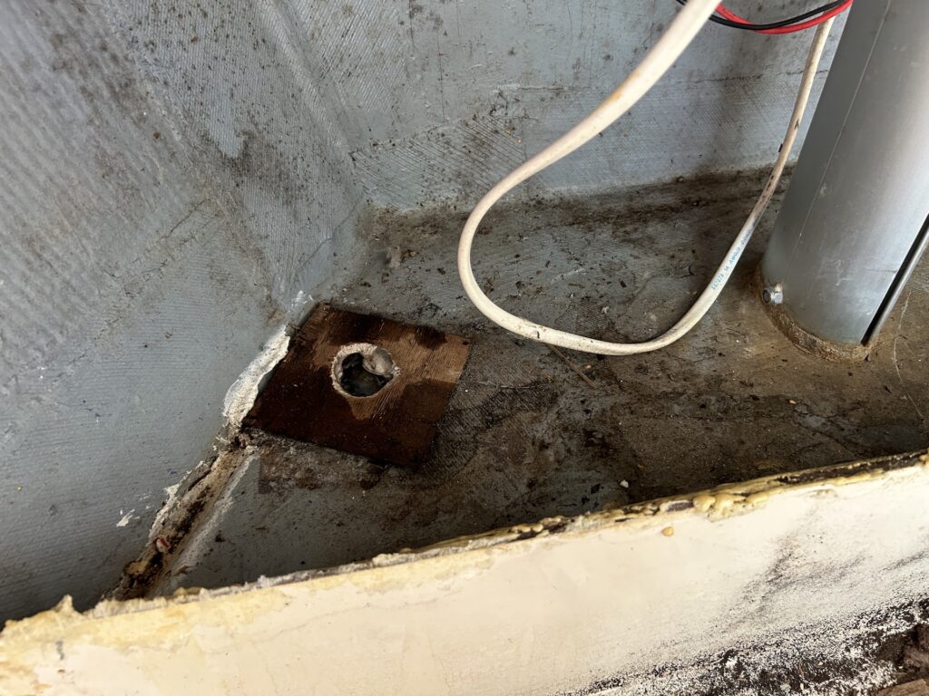
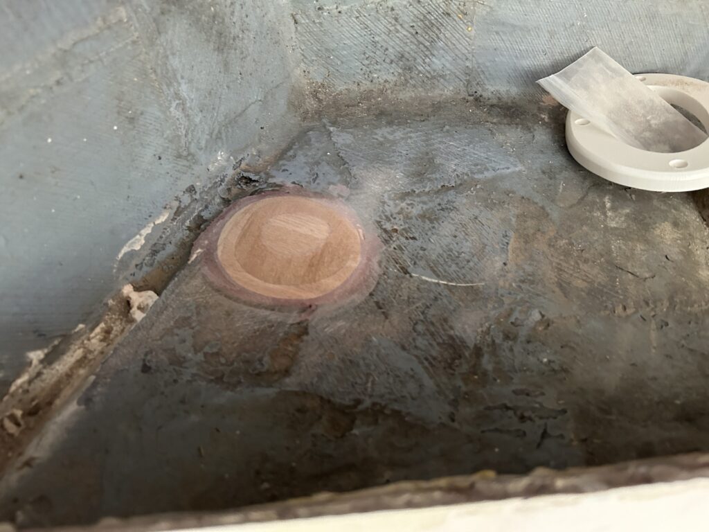
Two more such holes were found a bit forward. Here is one on the port side that you can also see in the image above.
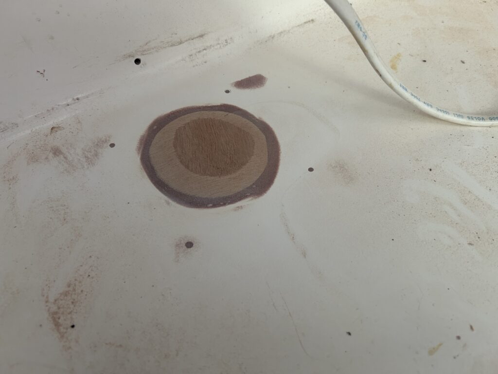
Obviously the rotten covers to these holes needed to be removed and replaced.They were replaced with 3/8-inch marine plywood and bedded in thickened epoxy.
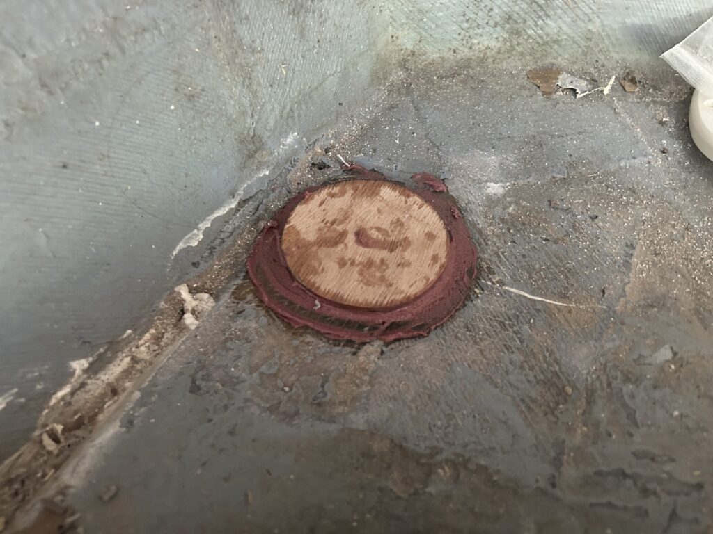
After the epoxy dried, they were sanded down to make them blend.

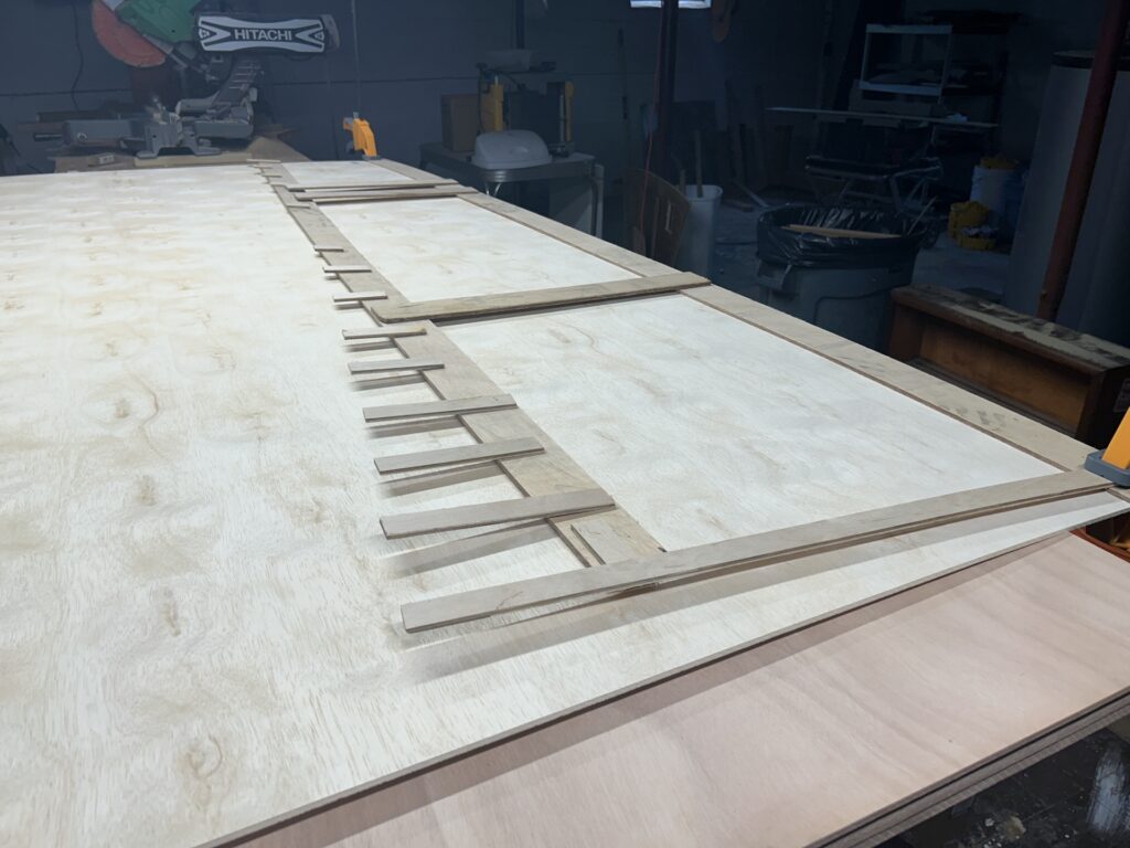
Meanwhile, work began on the new walls, which will be made from 1/4-inch marine plywood, painted white. Here a template for the port-side wall is being made, using a tried-and-true method that utilizes thin strips of wood and a hot-glue gun.
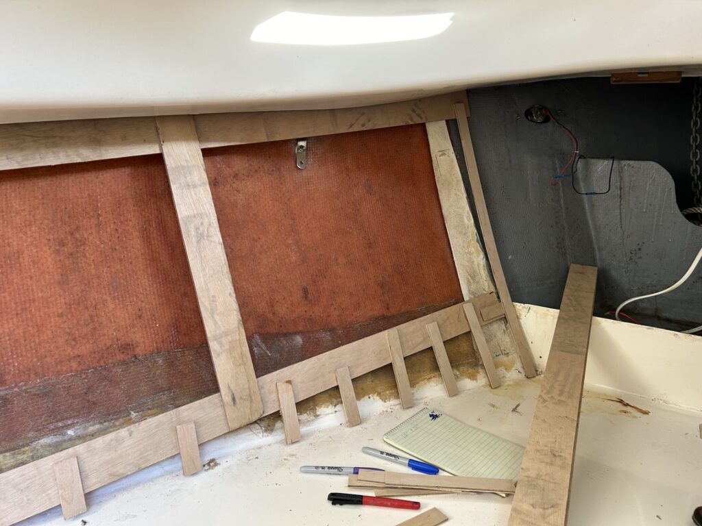
The walls will bend, and will be set away from the hull with blocks. We didn’t trust that the template would give a perfect fit, so the pattern was transferred to 1/4-inch cheap plywood, purchased from the local box-store.
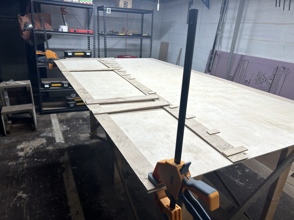
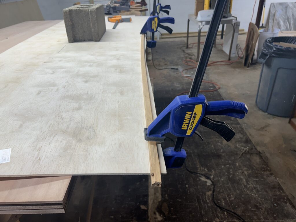
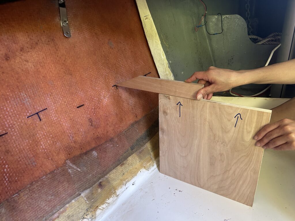
The walls follow the curve of the hull, and need to be attached to the hull somehow. I decided to epoxy blocks against the hull, into which the walls can be screwed, The mock walls seemed to fit well, so I moved on to working out out the block arrangement on the hull. I decided to space them evenly fore and aft at about 12 inches apart, and keep them at a uniform height above the seat level. Screw heads and washers will be visible from the cabin so considering the aesthetics is mandatory.
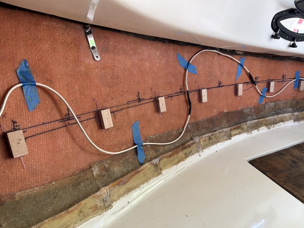
Here are some of the port-side blocks. The challenge in epoxying the blocks against a near-vertical surface is keeping them from slithering down the hull before the epoxy sets. I avoided this problem by setting them 3/4 in thickened epoxy (which dries slowly) and 1/4 in hot glue (which dries in seconds).

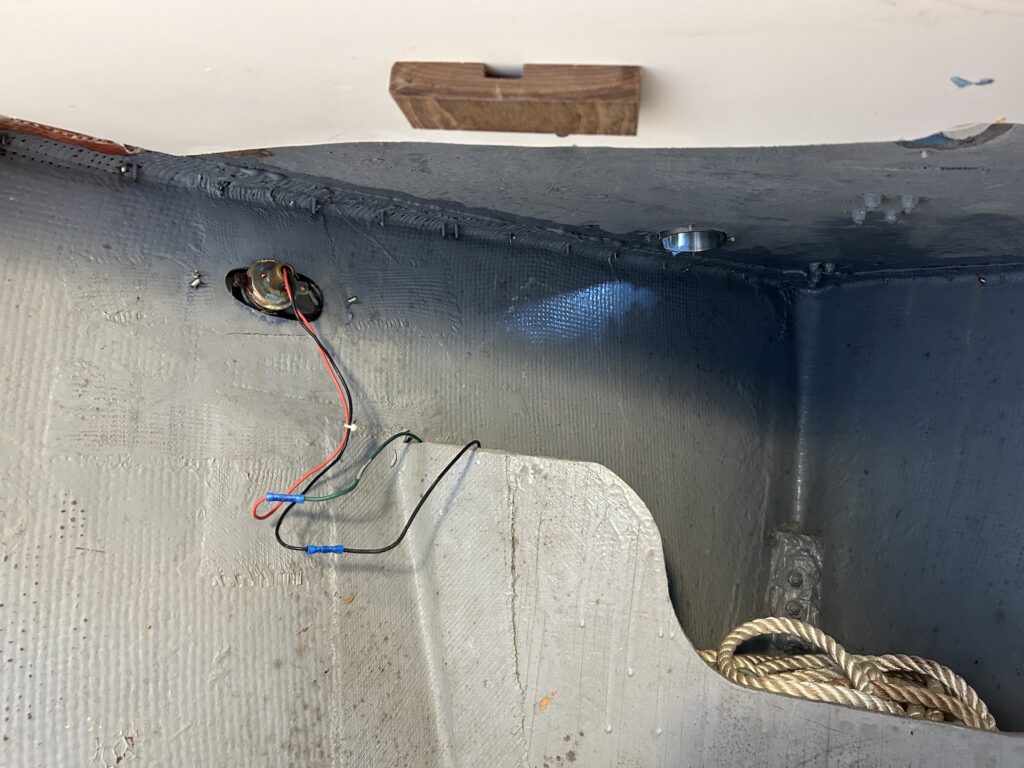
More on the electrical later, note that the wiring along the starboard side includes a number of splices, which suggests that the builder or a previous owner was short on wire at one time. This wire runs from the electrical panel to the stern light.
After the epoxy set up, I moved on to working out the screw-hole locations on the walls. This was a real challenge. The blocks are totally invisible and inaccessible with the walls pressed against the hull. The screw holes in the walls, on the other hand, need to find, precisely, the geometric center the corresponding block. After some brainstorming, I landed on the following solution: (1) Make a simple jig to drill small holes perpendicularly into the center of each block, and with a specific depth. (2) Place a brad nail, head first, into each hole. (3) Bend the mock-walls into their desired position. (4) Whack the mock-walls with a rubber mallet at approximately each block location. (5) Take off the walls carefully and find the brads no longer in the blocks, but in the desired location of the screw holes on the hull-side surface of the walls.

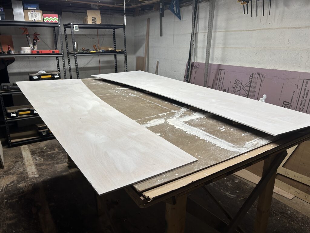
Next I cut the “real” walls out of 8-mm marine plywood.
The owner decided to replace all of the incandescent bulbs with LED: The stern light, starboard and port bow running lights, mast light, and dome light in the cabin.
We removed the mast as a means to check the mast step (it is fine) and replace the deck collar. The mast is stepped in the forepeak, so its removal facilitated working in the area.

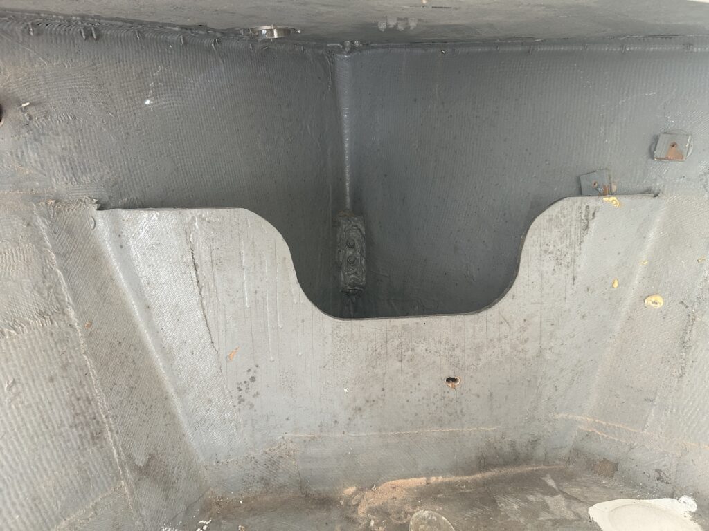
With everything removed I was able to get the entire area forward of the bulkhead cleaned and painted with a fresh coat of gray Bilgekote. This is the BEFORE picture:
A template was made for the bulkhead. Note that the unpainted walls are installed at the time.
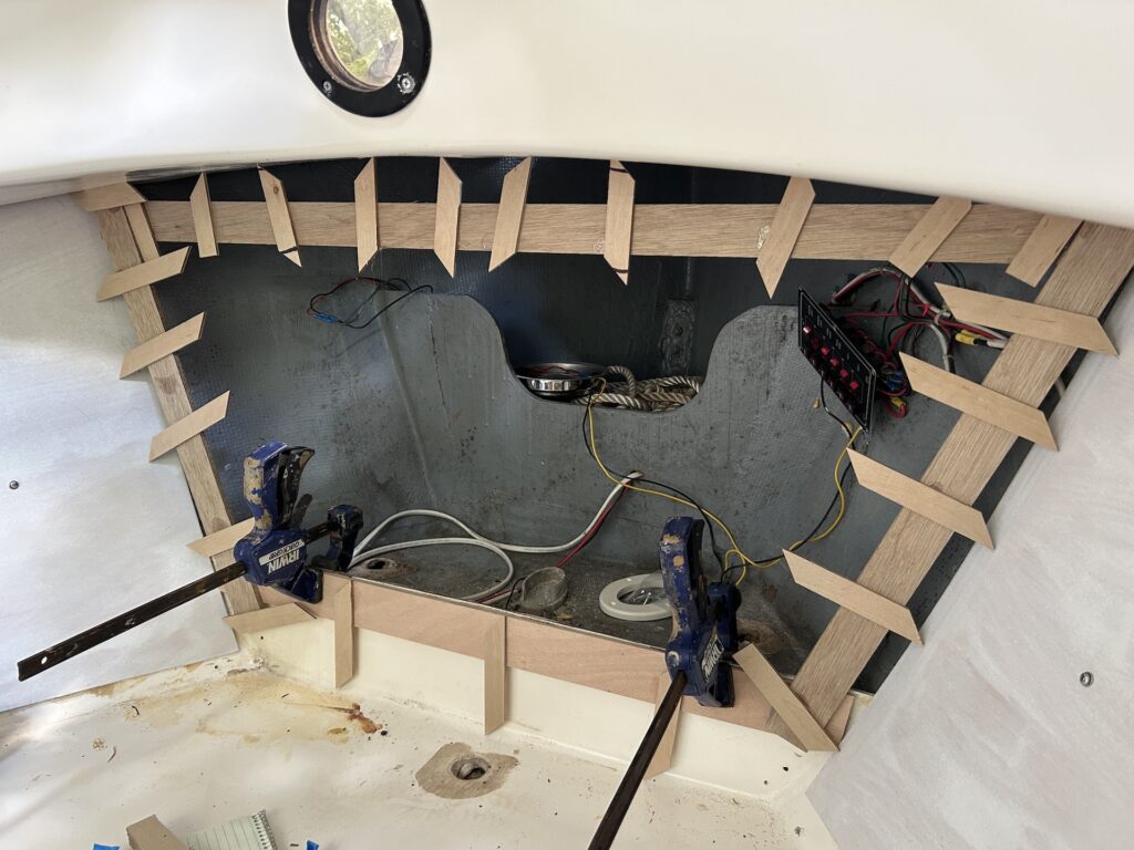
We cut a mock bulkhead out of cheap plywood. I wasn’t happy with the fit of the mock bulkhead so we “scribed” the walls onto the mock bulkhead.
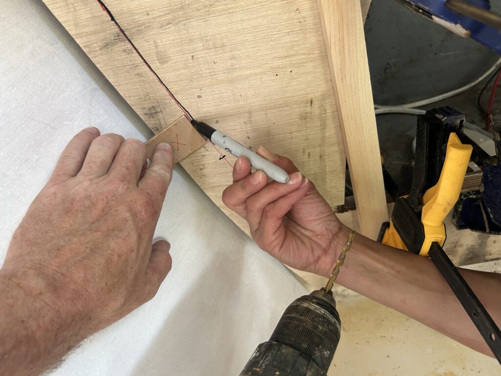
We boldly transferred the scribe line to the good plywood, in this case 5/8-inch marine ply:

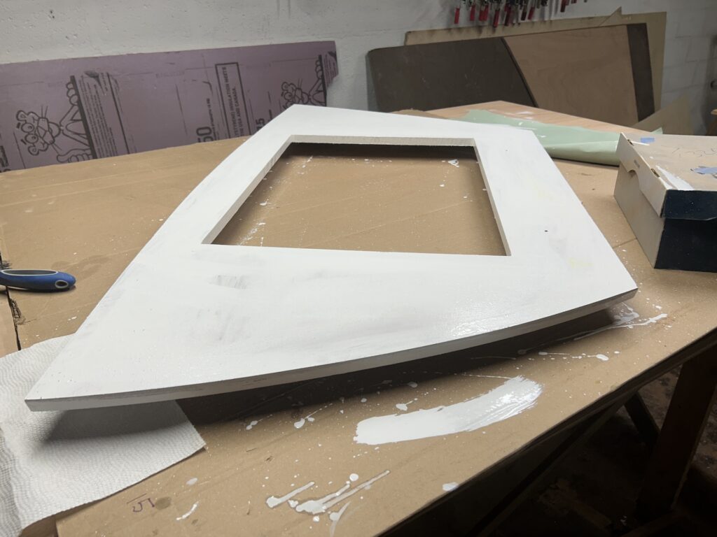
The fit was pretty good, and after a few iterations of checking and shaping the fit was very good. At this point it was ready for primer:
I had some nice hinges left over from another project, and I used them here. The original bulkhead has one small door, and to improve access and aesthetics we decided on two doors:

The trim was made with teak I had leftover from another project. I made the U-shaped trim pieces utilizing lap joints. The lap joints must be glued up (with epoxy) in a precise manner, so we utilized the doors and clamped them up to dry:
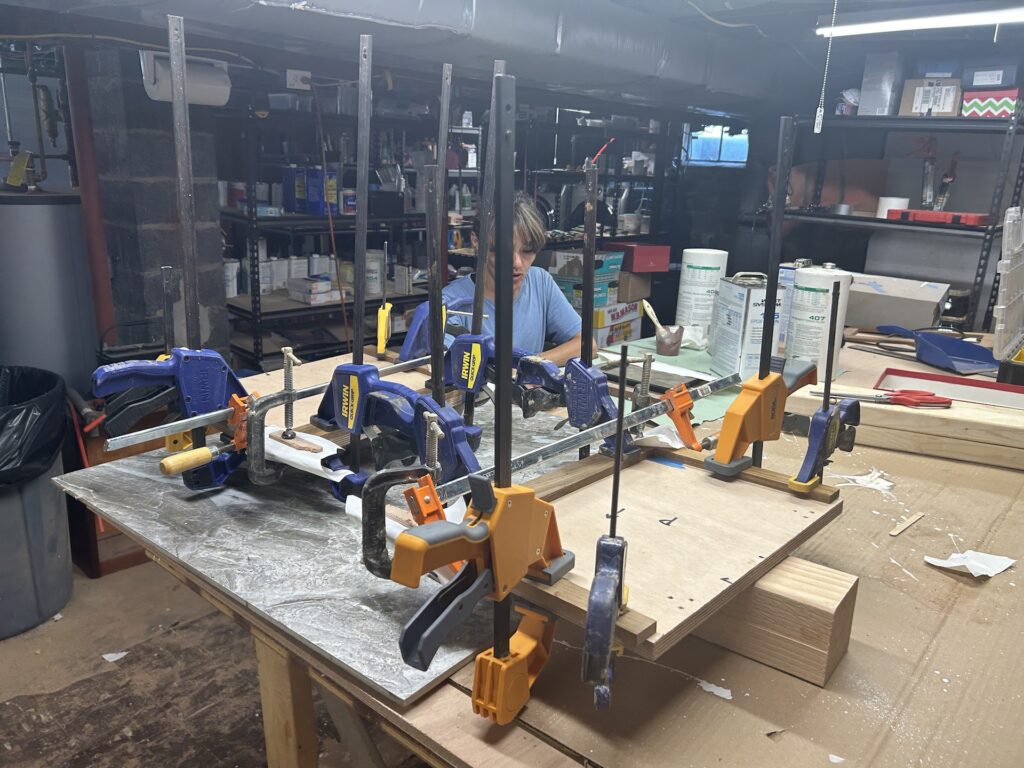
After 24 hours they were removed from the clamps:
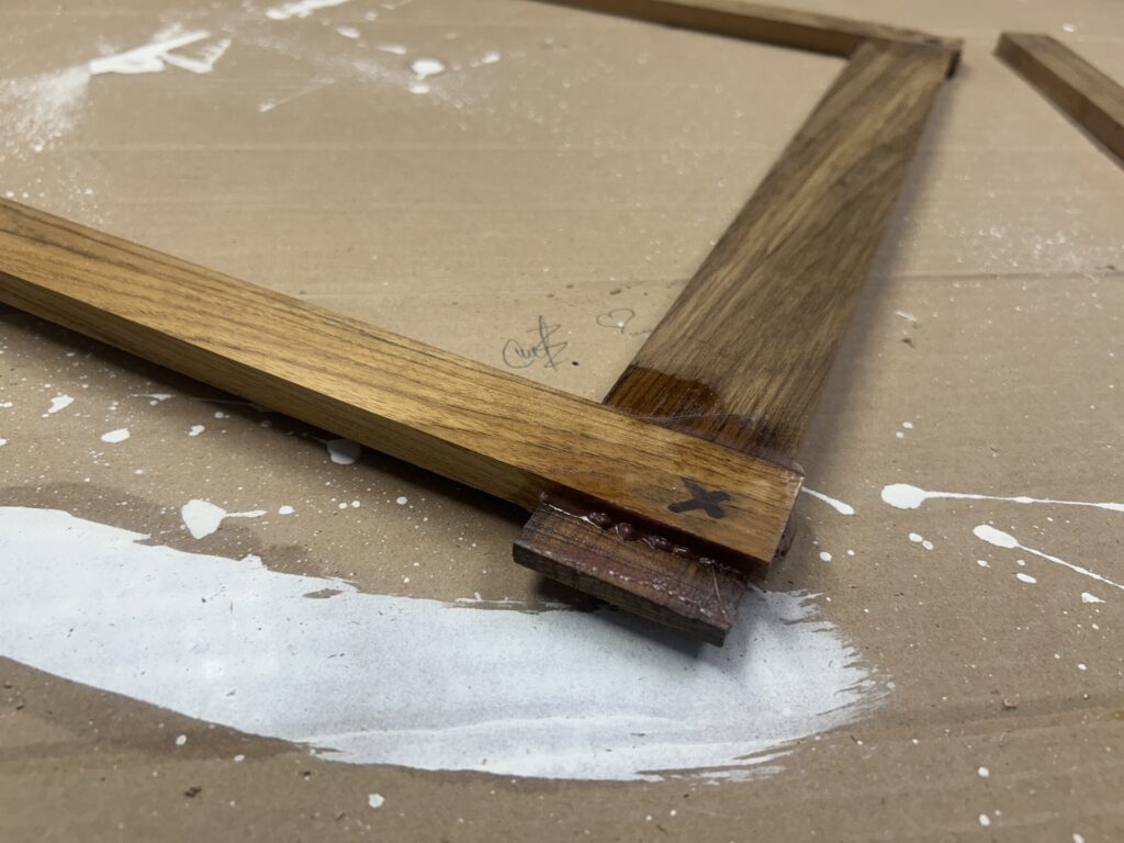
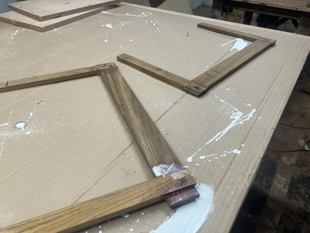
After cleaning up the pieces, we had to work out their position relative to each door. The trim will be fastened by screws that pass through the doors from their back sides. The challenge here was to be able to maintain the correct position of the trim exactly while opening the doors so that pilot holes could be drilled. I solved this problem by gluing blocks in the corners, as shown below. (Note that the temporary blocks are glued to tape for easy removal.)

After the pilot holes were drilled, the outer edge of the trim was rounded over with a router and then sanded. Afterwards I applied the first of six coats of varnish.
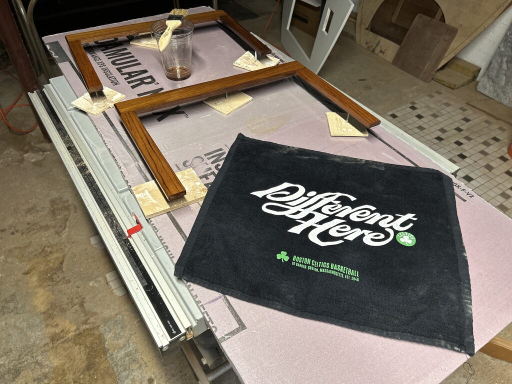
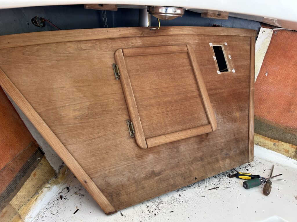
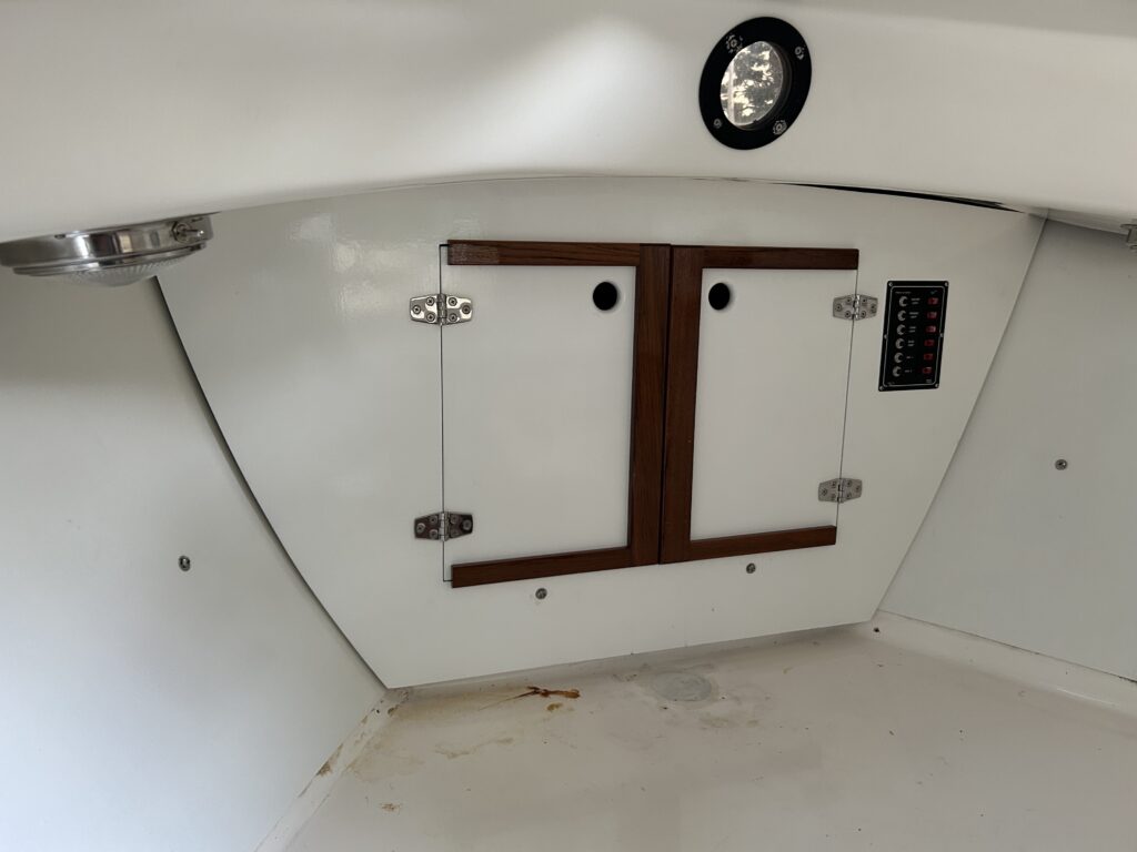
Fast forward a bit, and the bulkhead doors are complete. Behind the finger holes are elbow latches, whereby an inserted finger can open the door. Note also the hole for the electrical panel.

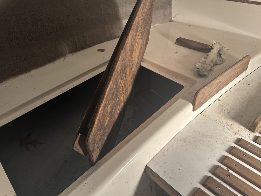
The easiest job of the project, by far, was making new storage-compartment lids to replace the dilapidated originals. Here is one of the originals:
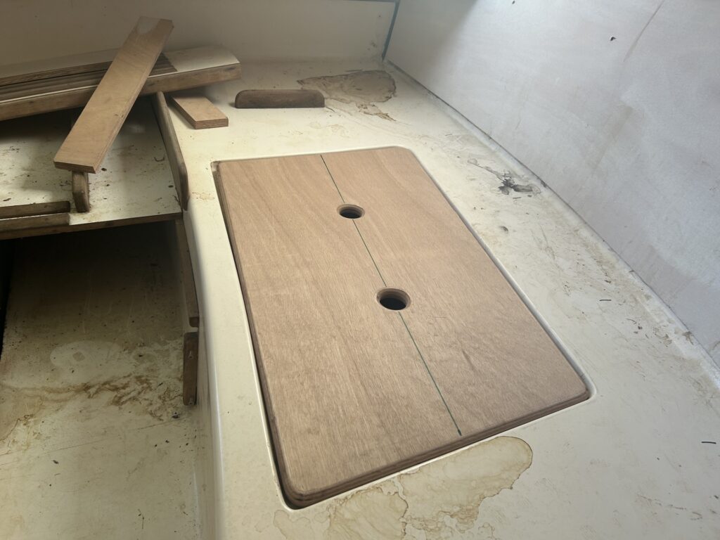
The old lids made suitable templates for the new. There are two improvements in the new lids (besides being not-dilapidated): (1) I added finger holes to facilitate lifting and (2) I used thicker (and better) plywood for more strength and, as an added bonus, the thicker plywood corresponds to the tops of the lids bing even with the surrounding area.
The bilge pump was not working, so the owner ordered a new rebuild kit, which consisted of a new diaphragm and two flapper valves.
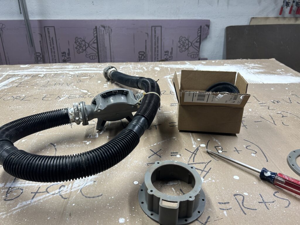
Upon dismantling the old pump, I found that the old parts, while worthy of replacement, were basically intact and functional, and thus began the mystery. (The image below shows the two new flapper valves in the foreground.)
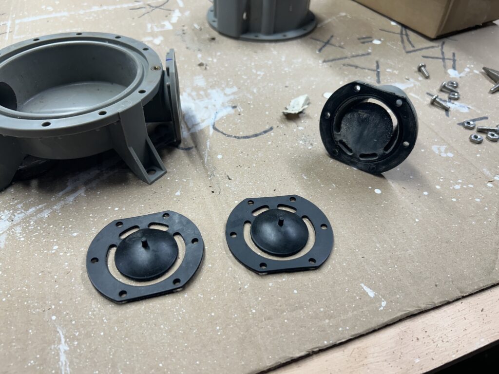
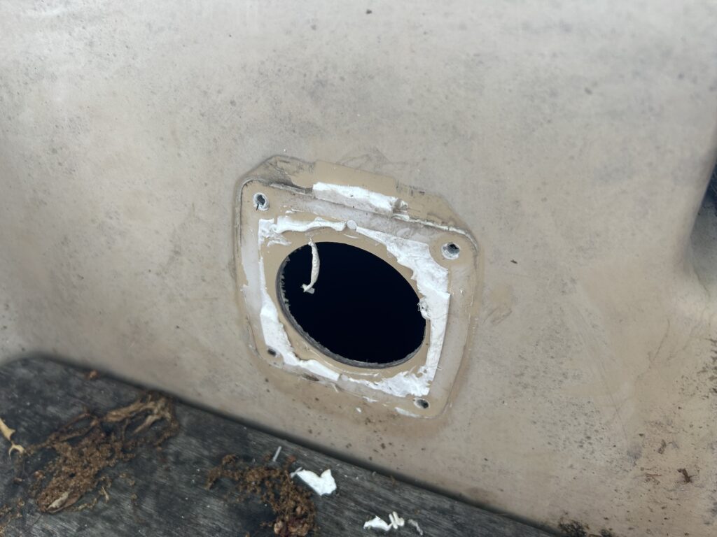
Forging ahead, I removed the pesky sealant that sealed the exterior parts of the pump system.
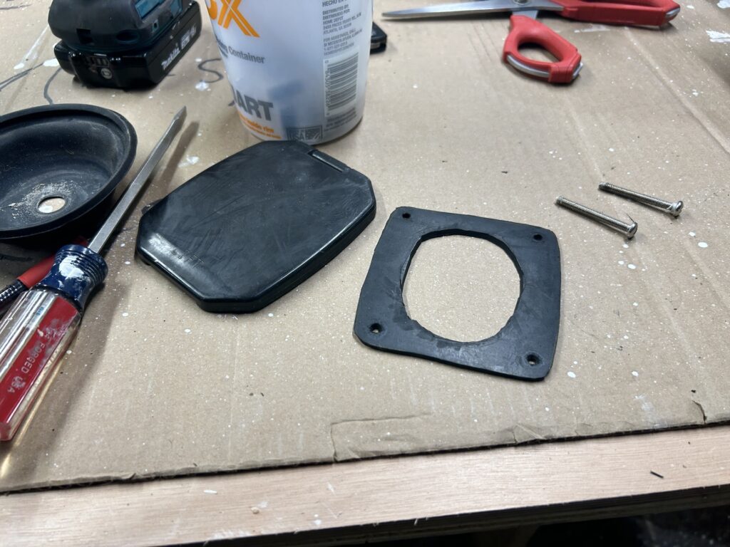
Instead of using sealant in the rebedding, I made a gasket from some gasket material I had leftover from another project.
After I put together the pump and reinstalled everything, I found that the pump worked reasonably well, but then failed after a short time. I took everything apart again to find that there were stones lodged in the flapper valves. As it turns out, there are small stones in the bilge (another mystery) and in trying to pump them through, they can foul the mechanism. I recommended to the owner that we install something on the bilge-end to filter out large debris.
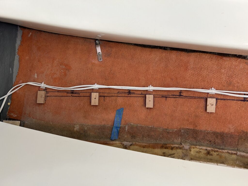
The electrical system consists of a 12-V battery, running lights (stern + port/starboard bow), mast light, cabin light, and an electrical switch panel. The stern-light wiring runs along the starboard side, under the cockpit, and along the hull. This wiring contained a number of splices, suggesting that either that the manufacturer was short on wire during the original build, or that a previous owner somehow deemed necessary splitting up a continuous length of wire into sections. In any case, now is the time to replace with a continuous wire.
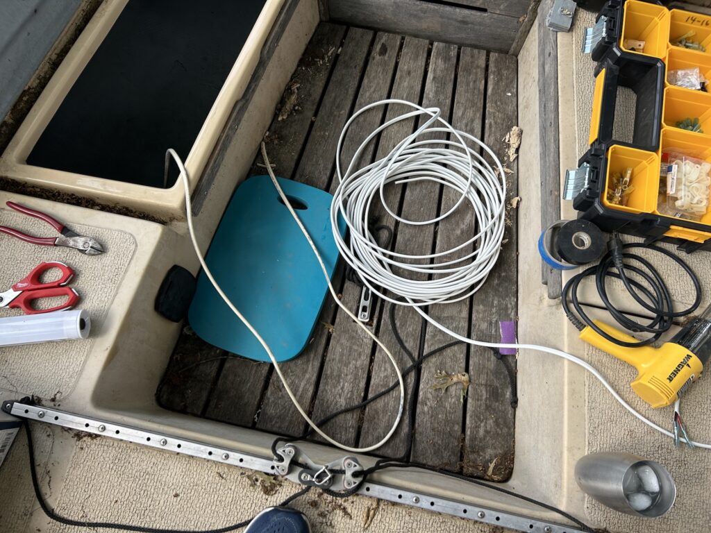
Here we’re preparing to make the run from the stern light to the forward compartment.
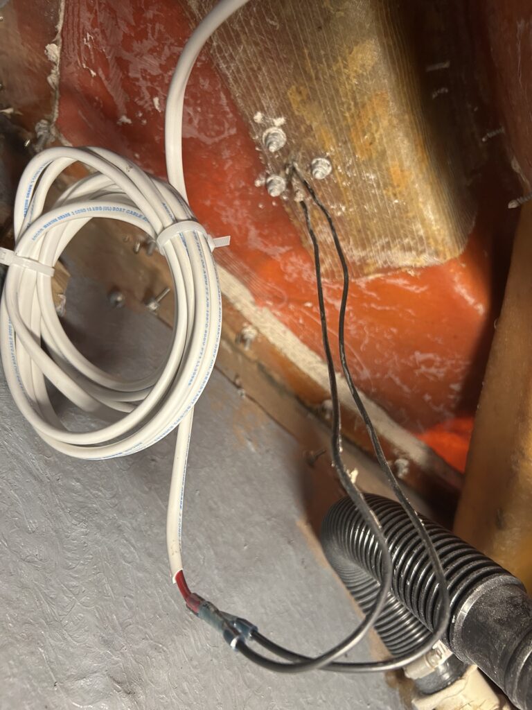
Pictured below is the aft end of the run. The black wires run through the deck and up some stainless tubing to the stern light. I decided to NOT replace the black wiring, considering the additional work and time involved, but I left enough extra new wire coiled up so that one could complete the run on the aft end with the new wire.
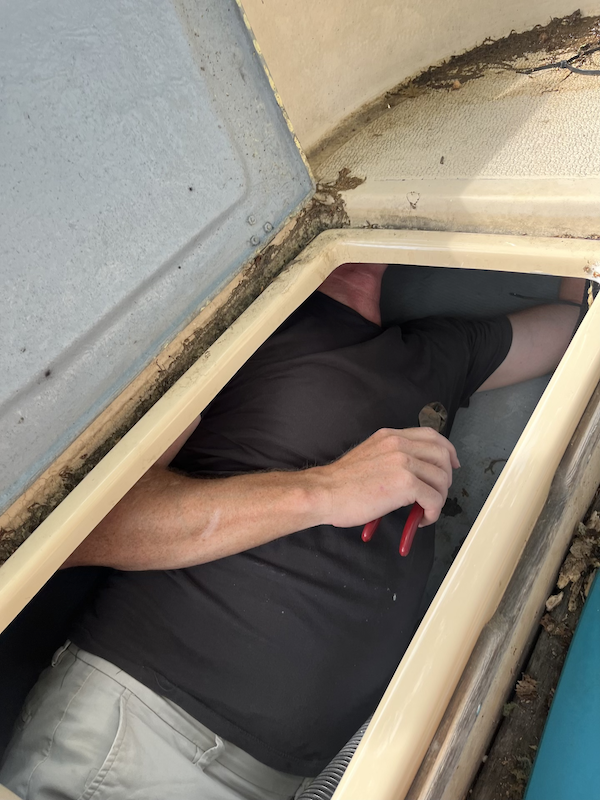
I was just barely able to get into the space under the cockpit.
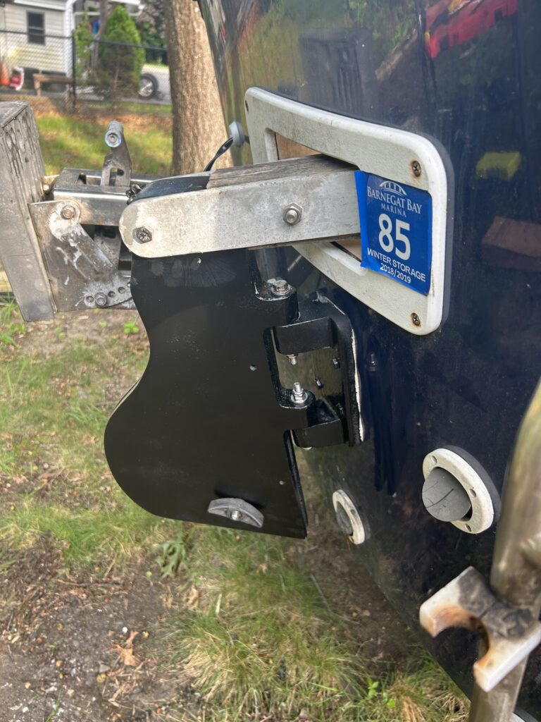
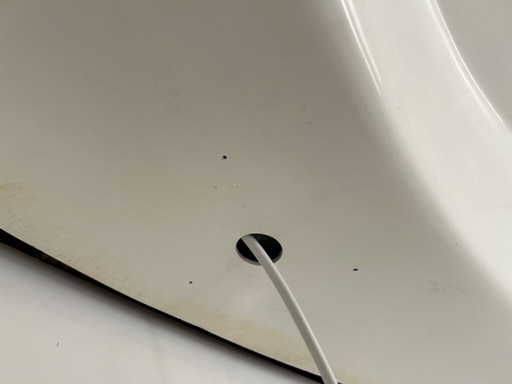
The owner purchased a new outboard motor–one with an alternator for charging a 12-V battery. This required another wire to be run from the stern to the bow. In this case, I installed a small through-hull, through which the aft end of the wiring harness protrudes:

Pictured below is a look from the inside.
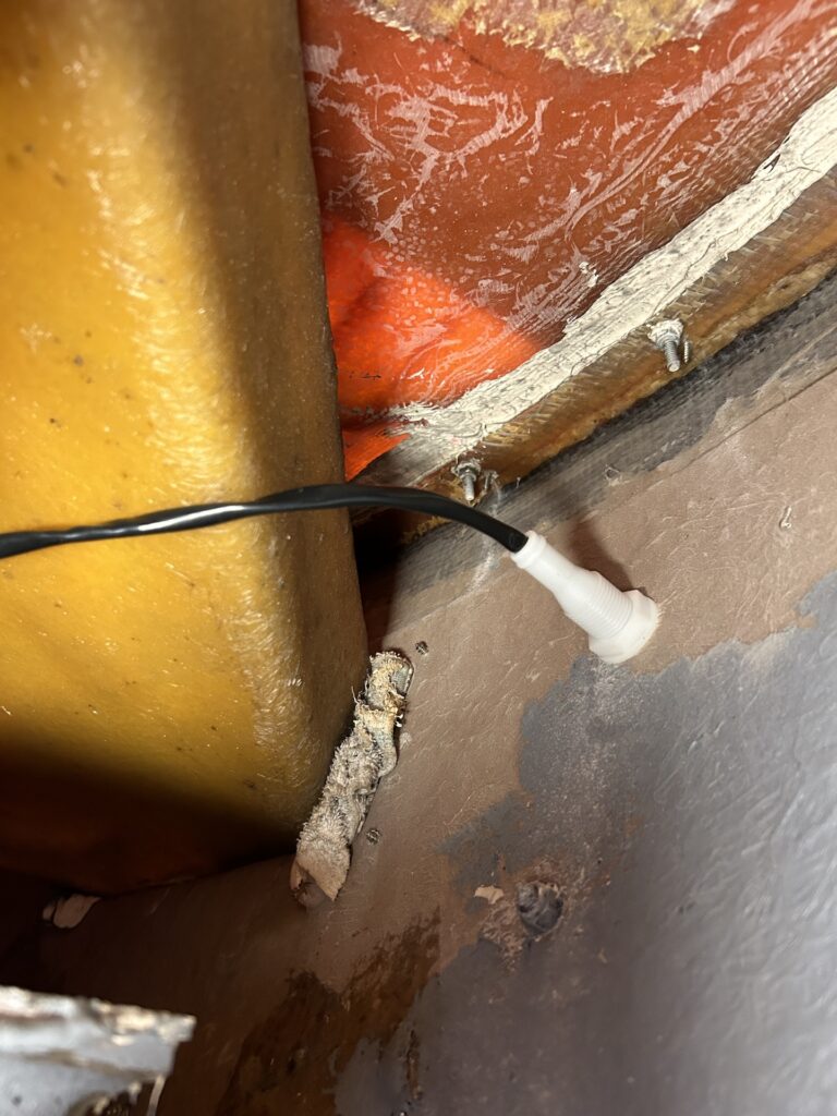
The wiring harness is nowhere near long enough to reach the bow, so I spliced on and ran a separate wire. The stern-to-bow wiring now consists of two wires. Here is the part of the run that is behind the starboard-side wall:
The owner purchased a new 12-V battery and a battery box/holder. The previous box was essentially the same, with four holes for screws at the four corners, and a battery hold-down mechanism. The previous box, however, was only screwed down in three places. You can see below that the forward-outboard corner of the box is precariously close to the hull, which is why no screw was used there with the original box. I added a fourth screw with a fender washer inside the box and safely away from the hull. This will provide additional tip resistance when heeled over on starboard tack.
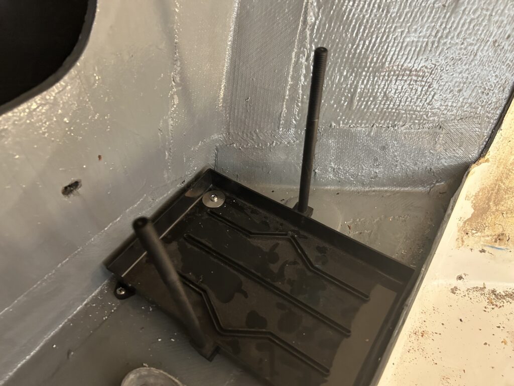
The battery didn’t quite fit snugly in the box, so I glued some small wood blocks in to the side of the battery, as shown below.

Meanwhile, during some cockpit cleaning, I unlashed the rudder and found that it could be moved only with significant torque. There are gudgeons on both the rudder stock and the stern, and they are joined by 5/16″ bolts. You can see the arrangement below.
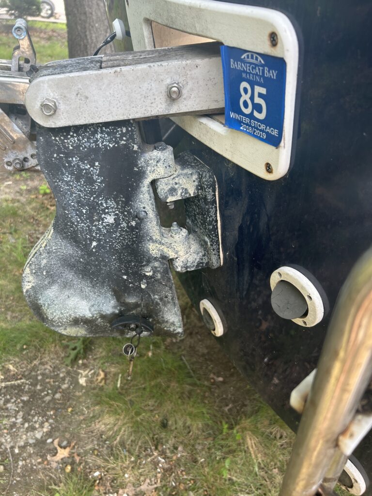
I started by removing the rudder.
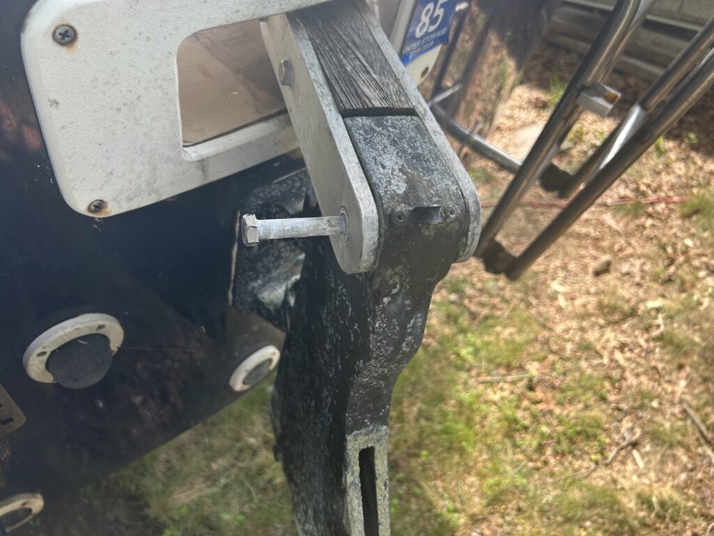
The bolts were almost seized and I was unable to remove them with wrenches. Eventually I cut them off and hammered them out. I used various sanders to clean up the aluminum pieces, which were significantly oxidized, despite having been painted black.
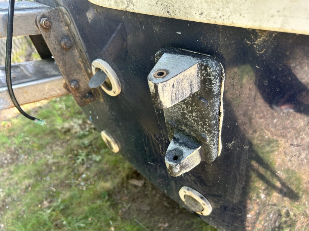
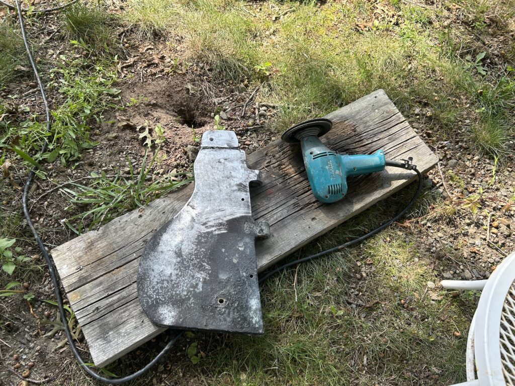
After the metal was clean, I applied a coat of “self-etching” primer (which supposedly makes for a secure bond with the paint layer, preventing the kind of oxidation I removed.
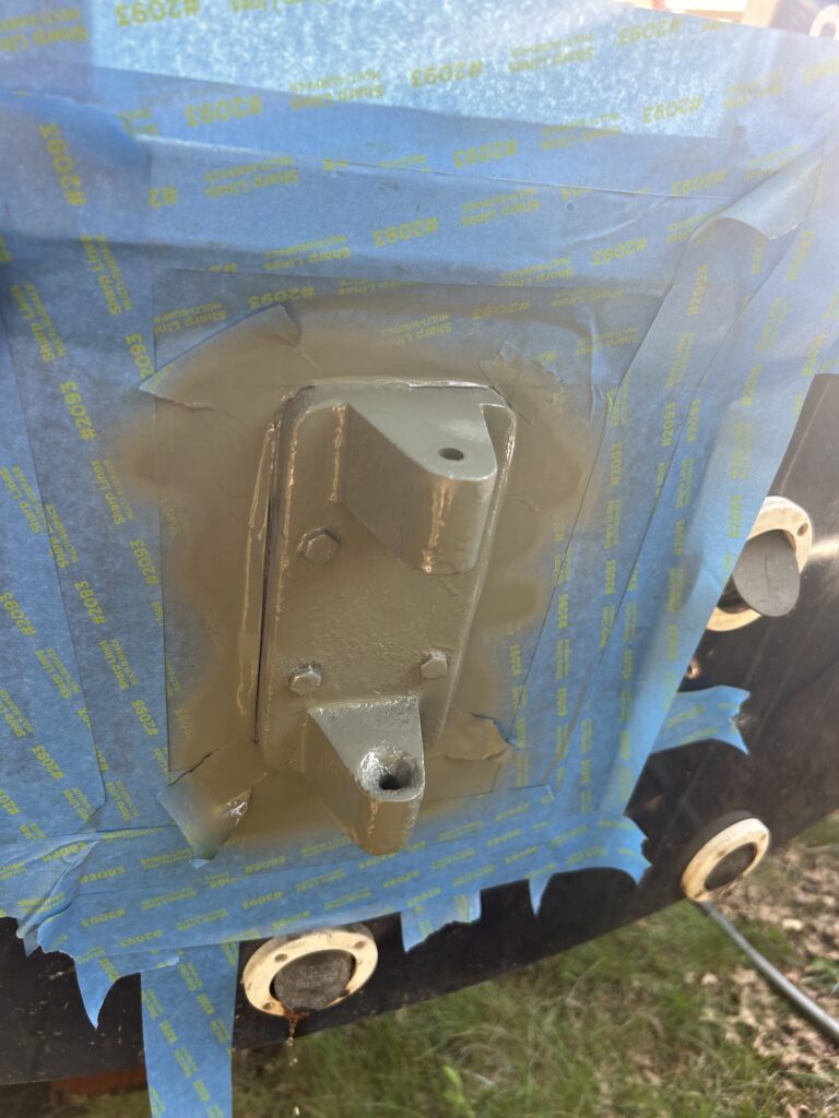

After the recommended dry time, I painted black.
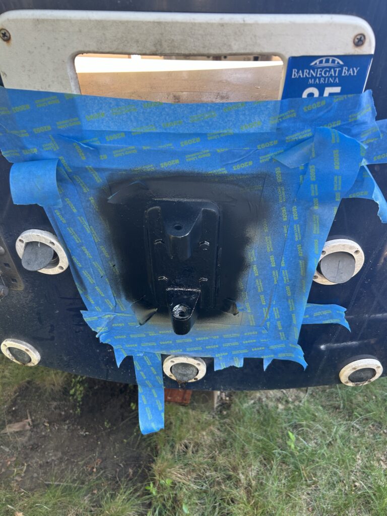
I reassembled with all new bolts, nuts, and washers, and I used white teflon grease for lubrication. Now things are not only looking much better, but the tiller moves with no effort.
The original layout included one dome light in the cabin, mounted directly bedind the bulkhead. We decided that two new white/red LED dome lights would be mounted elsewhere. The one on the starboard side will go here:
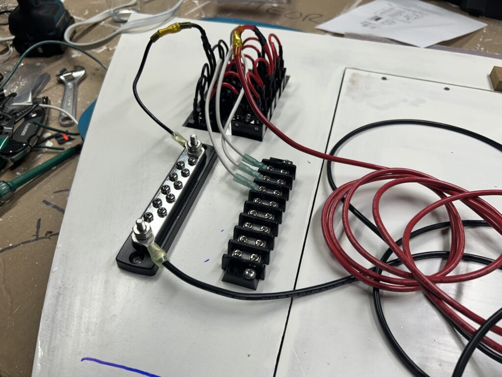
The new switch panel was installed in the bulkhead, as well as a terminal block and negative bus bar. Everything can be wired drectly to the panel, but utilizing the bus. bar and terminal block can simplify certain aspects of troubleshooting and adding new circuits.
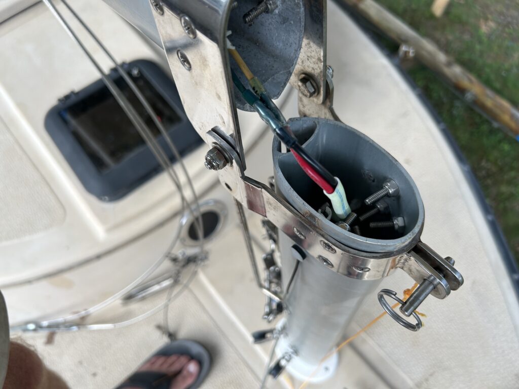
The mast was installed and new wire was run from the mast join down into the boat.
The wiring at the battery end of the circuit. A little further tidying up with zip ties will make a neat presentation.
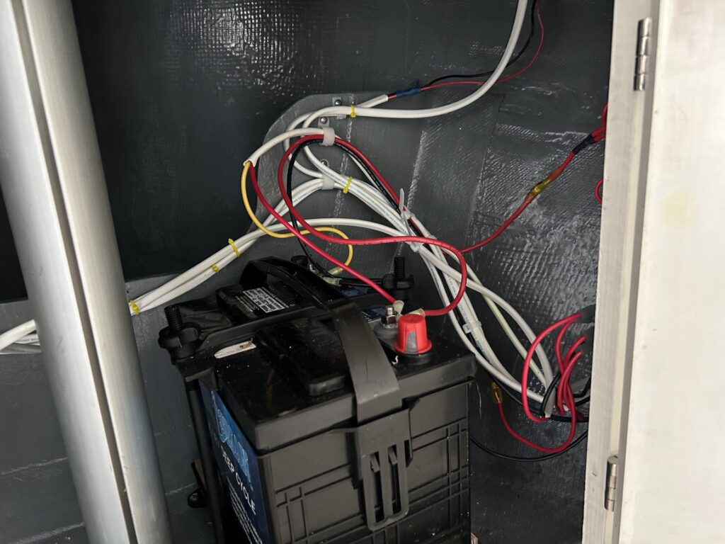
The inside of the port and starboard storage lockers needed some sanding and fresh paint.
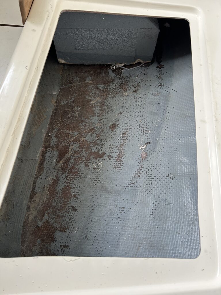
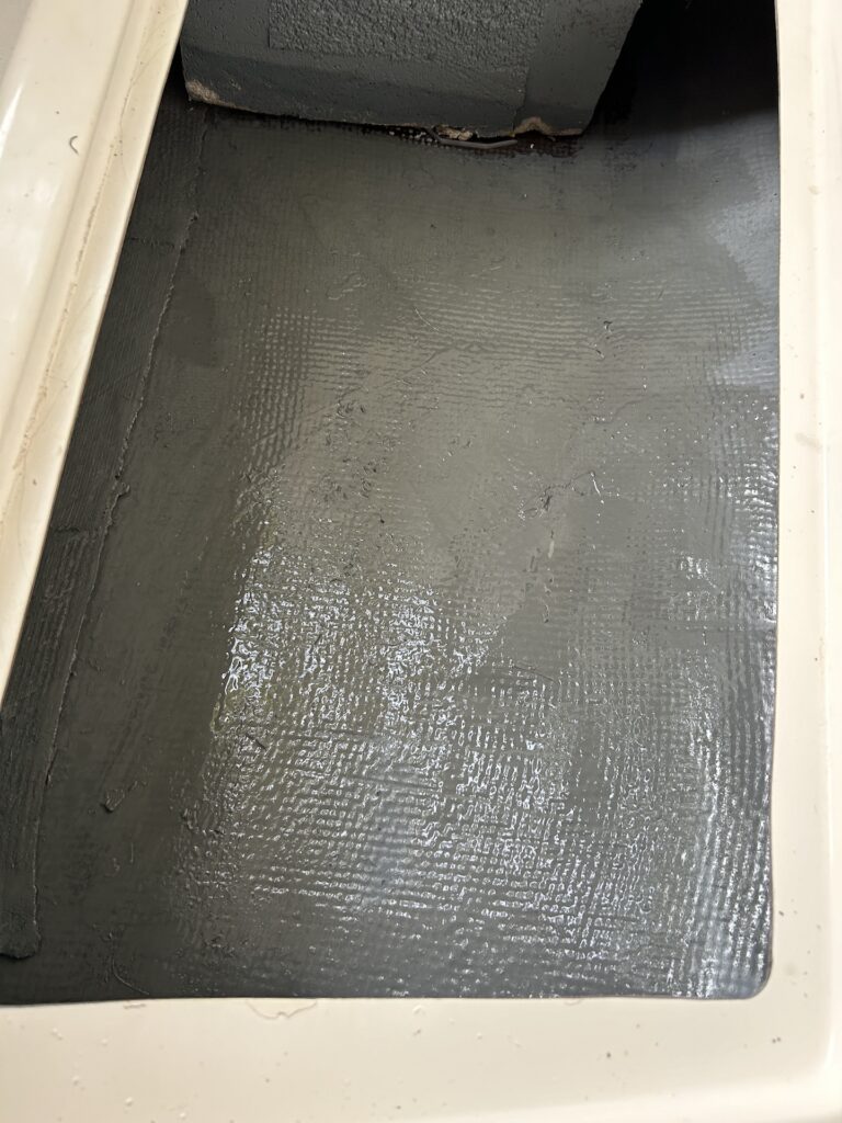
Finally the project is essentially complete and the boat is ready for the owners to pick up.
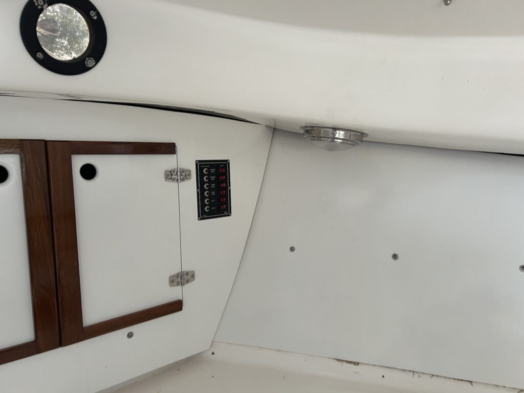
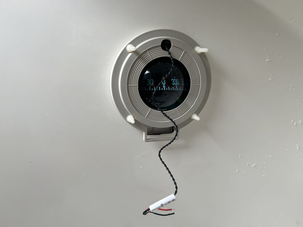
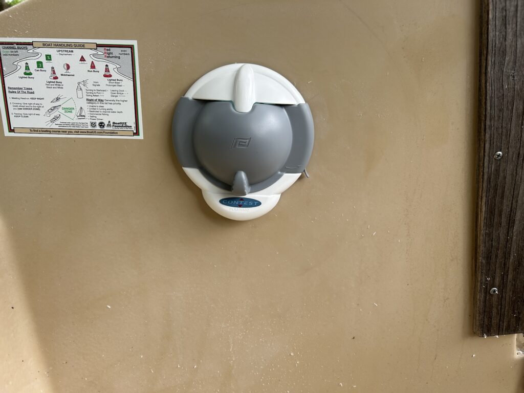
Not so fast. I forgot to install the new compass. The bolt holes for the new compass matched those of the old, but the cutout did not. The new compass came with a cutout template/sticker, which I stuck to a piece of scrap plywood to make a routing jig.
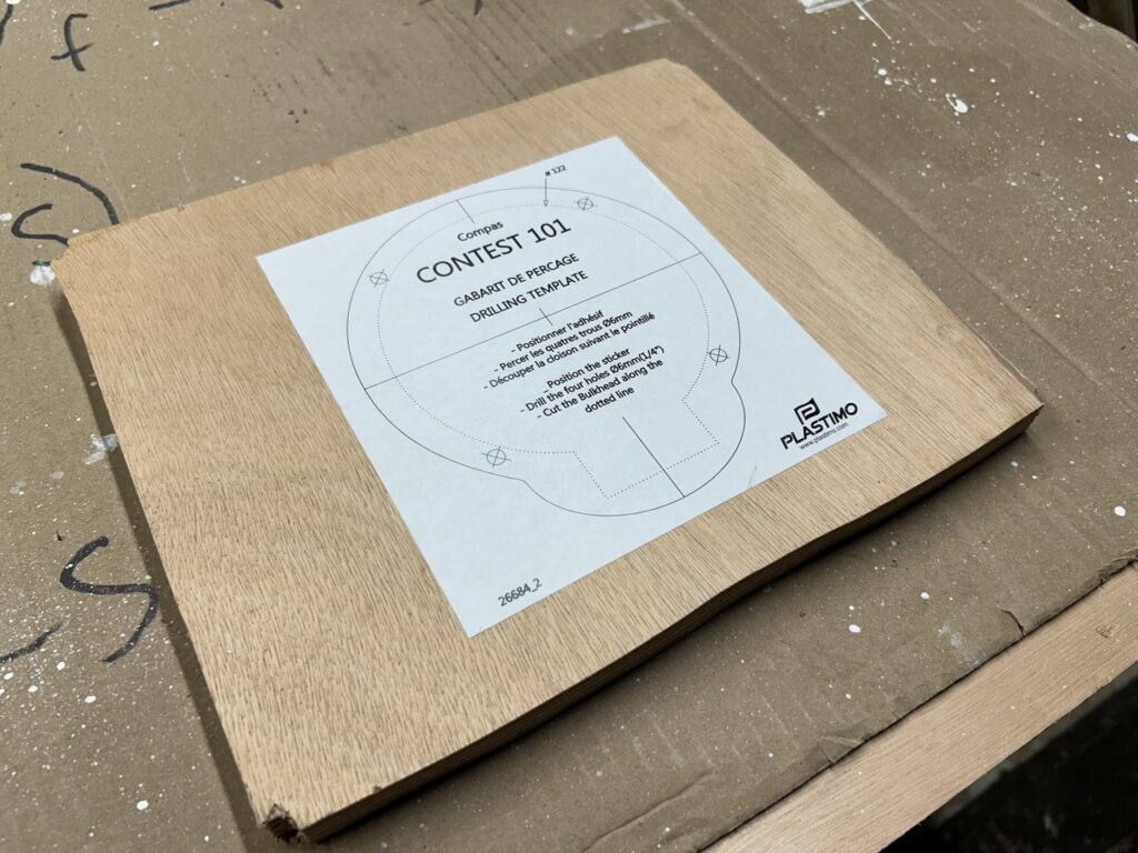
Next, I used a jig saw to cut closely to the dashed line, which defines the cutout. My oscillating belt-and-spindle sander can be used as a belt or spindle sander. I was out of spindle sandpaper, so I was forced to use the belt function. To do so, however, I needed to cut the jig in two pieces. In this way I was able to use a semicircular end of the belt to complete the shaping.
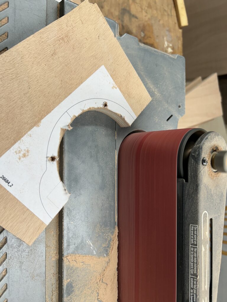
Next, I glued the jig back together, being sure to use thin strips of wood to account for the blade-width of material lost in cutting it into two.
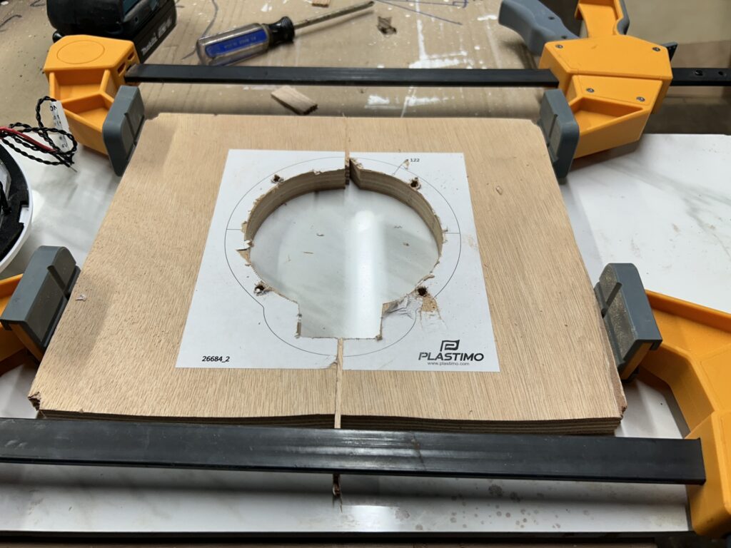
I drilled holes according to the template and countersunk them. Next, I screwed the jig to the boat utilizing a backing plate of thin plywood.
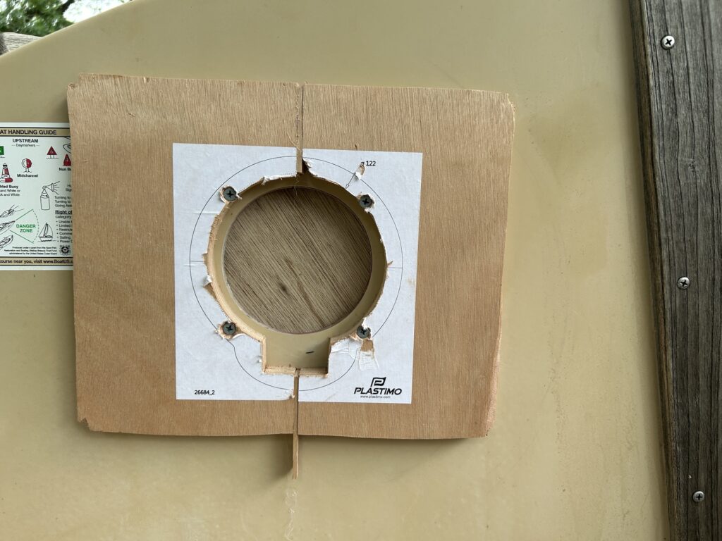
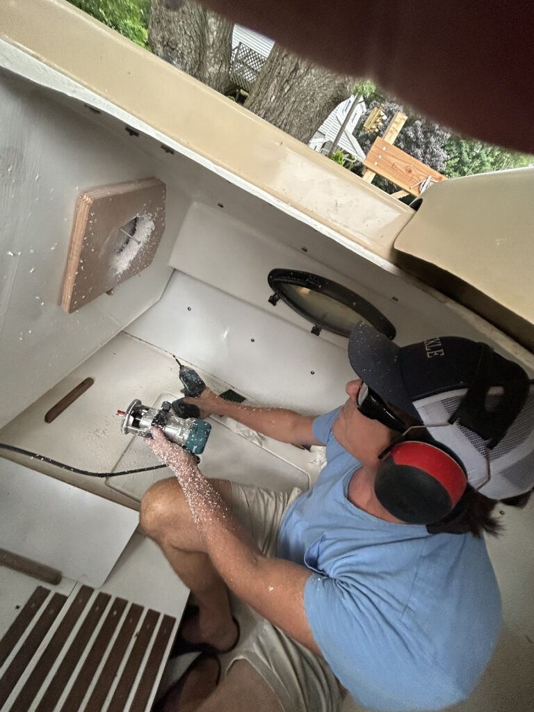
The routing commenced:
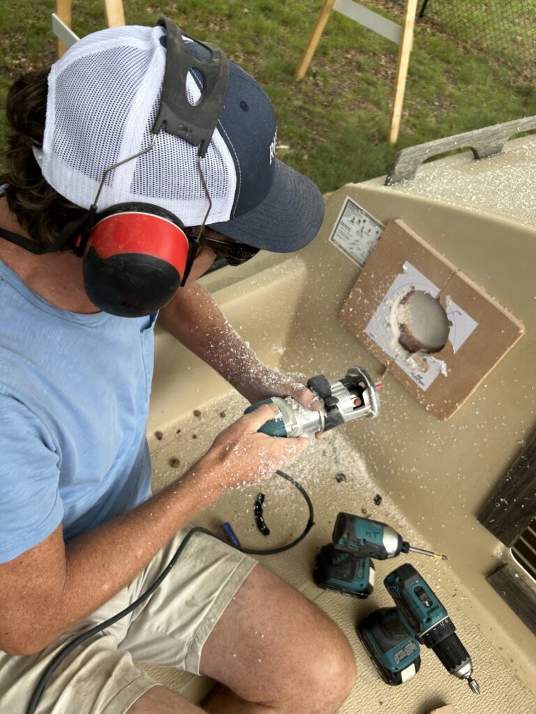
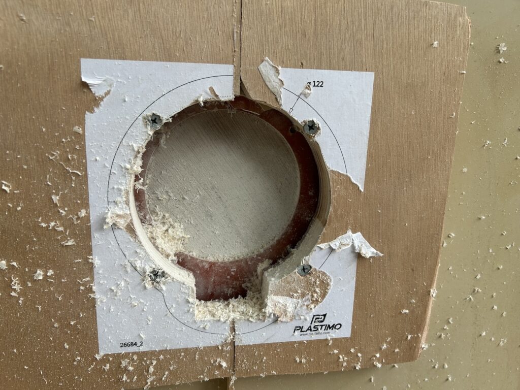
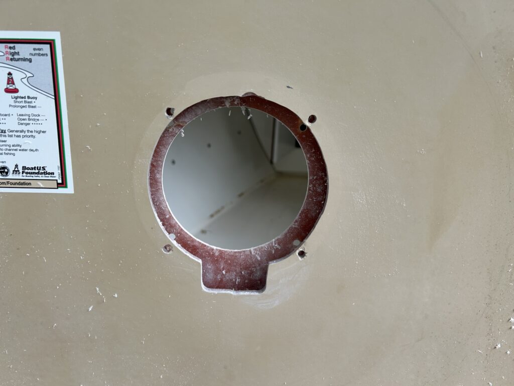
We found that we had to repeat the process from the inside.
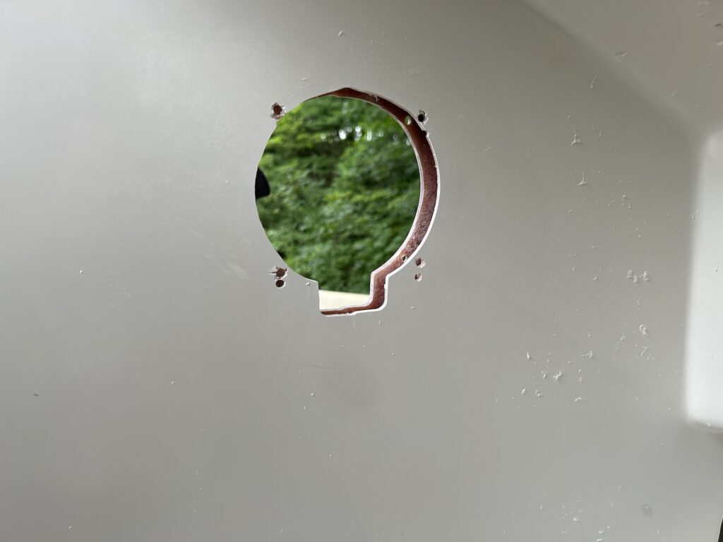
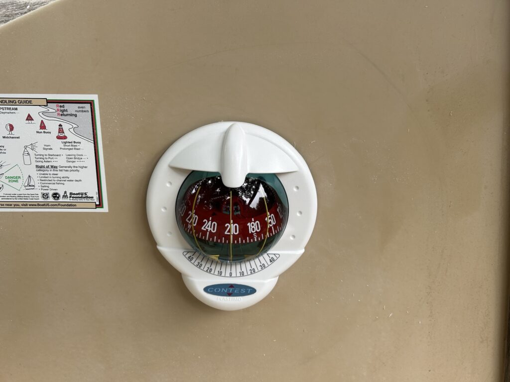
Here is the final installation. The compass light may be added to the circuit in a future project.
